


Read the Full Series
This article is one part of a walkthrough detailing how we recreated an NXP i.MX 8M Mini–based computer using Quilter’s physics-driven layout automation.
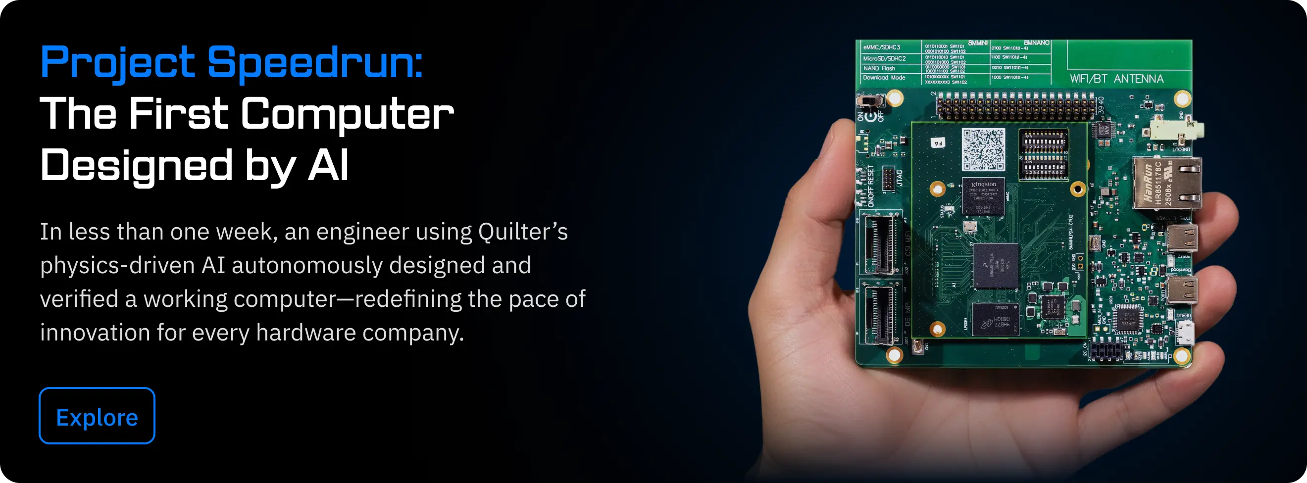
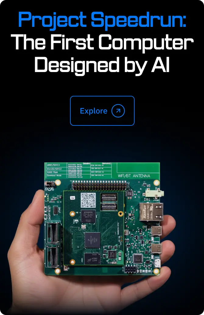
Project Speedrun is our challenge to design a complete computer using our physics-driven AI as quickly as possible. This blog series documents how that system was developed and the engineering decisions behind it. Start with the Project Speedrun overview and its results.
The i.MX 8M Mini platform used here is the same class of board found in automotive, aerospace, industrial control, and safety-critical products—making it an ideal test of whether a physics-driven AI can deliver reliable hardware.
The Project Speedrun boards Quilter designed required only 38.5 hours of human polish, rather than the 428 hours quoted for a fully manual layout. What happened next is the real measure: both the SOM and baseboard came back from fabrication, powered on immediately, configured DDR, expanded eMMC, and ran full system workloads on the first spin.
Power‑On: The Moment of Truth
Power‑on is where most electrical mistakes reveal themselves, and, if we’re honest, the part engineers are most nervous and most excited about.
We were eager to see the boards in action the moment they arrived from Sierra. Having already validated the baseboards using the known-good NXP EVK SOM, Ben opened the box on Google Meet and pointed the camera at the bench in his garage lab as he powered up the system. It was like Christmas morning; assembled SOMs and baseboards scattered on the desk and antistatic bags on the floor of the coolest garage lab you’ve ever seen.
In that session, using the very first boards out of the box:
- The SOM and baseboard seated cleanly.
- Power‑on produced no smoke, shorts, or brownouts.
- The SoC entered USB download mode on the first attempt.
- The board enumerated over USB and accepted a flashing command immediately.
It was two engineers too impatient to wait for a polished demo, opening boxes and plugging in boards; and the hardware simply worked! That matters because passing power‑on in a real‑world setting across multiple units confirms that the PDN, high‑current paths, decoupling strategy, and sequencing hold up under normal engineering behavior rather than just idealized lab conditions.
Boot Chain Validation (Does It Run?)
A compiler is trusted only when the resulting program executes correctly. The same applies here: an embedded computer layout becomes credible only when it boots and runs real software.
USB Flashing (uuu)
We first streamed a full Linux image over USB 2.0 into the SoC, writing it to eMMC using the Universal Update Utility (UUU). This tested the USB PHY, reset behavior, and PDN stability. Transfers remained clean throughout as we observed no disconnects, no retries.
First Boot
Switching to normal boot produced a clean sequence:
- U‑Boot launched immediately.
- LPDDR4 was detected and the link established at full 3GT/s speed.
- QSPI and eMMC initialized normally.
- Linux started without warnings.
Login and Filesystem Expansion
The system displayed a login prompt, accepted credentials, and completed a full expansion of the root filesystem to the 32 GB eMMC without timing or I/O faults—confirming stable storage routing and demonstrating the kind of successful, unassisted boot that establishes baseline reliability immediately.
LPDDR4 Behavior During Boot
LPDDR4 exposes SI issues more reliably than any other interface. This is not something that normally succeeds on the first spin.
The LPDDR4 host controller equalization and link tuning algorithms can compensate for small imperfections, but they cannot rescue fundamentally incorrect routing. The fact that DDR trained cleanly—detected immediately, completed without fallback, and handed off to Linux with no warnings—were consistent with expected behaviour and indicates that the memory channel’s timing, impedance, and via behavior were within system SI margins.
Full System Integration Under Load
Subsystems functioning individually is necessary but insufficient. True validation happens when CPU, DDR, GPU, I/O, and PDN operate together.
During bring‑up, the system simultaneously handled:
- CSI camera input
- LPDDR4 buffering
- 1080p DSI/HDMI output
- SSH over Gigabit Ethernet, USB/COM
- Interactive GUI activity
The system remained stable. No resets, no throttling, no underruns, no network stalls—and importantly, these were not simple functional checks. They were stress conditions under realistic load, the kind of scenarios that typically reveal weaknesses in PDN margin, SI behavior, or memory‑controller timing.
System‑Level Validation of High‑Speed and Real‑World Workloads
Each workload below appears in a tabbed scroller with associated video or logs. Together, these scenarios demonstrate electrical correctness and system stability under realistic use.
Multi‑Board Consistency
Multiple SOM and baseboard units behaved consistently during bring‑up. We take this to mean that the design itself is correct, and not a single unusually good unit functioning by chance. Flashing, power‑on, and early‑stage logs matched across units.
Remaining Validation & Future Work
Speedrun Computer passed bring‑up and real‑world workloads, but full product‑level validation extends further:
- PCIe link‑training and throughput
- Extended thermal and power characterization
- EMI/EMC scans
- High‑speed SI margining
- Long‑duration reliability testing
- Larger‑batch unit variability analysis
These steps are the natural progression for teams preparing mission‑critical deployments.
First-Spin Success Confirms What Automation Makes Possible
Speedrun Computer demonstrates that Quilter can handle complex, high-speed, mixed-signal designs; that its time savings hold in practice; and that the resulting hardware stands up under real workloads. We identified areas for improvement—SI margining, PCIe characterization, long-run reliability—but none blocked build or bring-up.
With Quilter, teams can turn a quarterly design cycle into a weekly loop of experiments, learning, and progress.