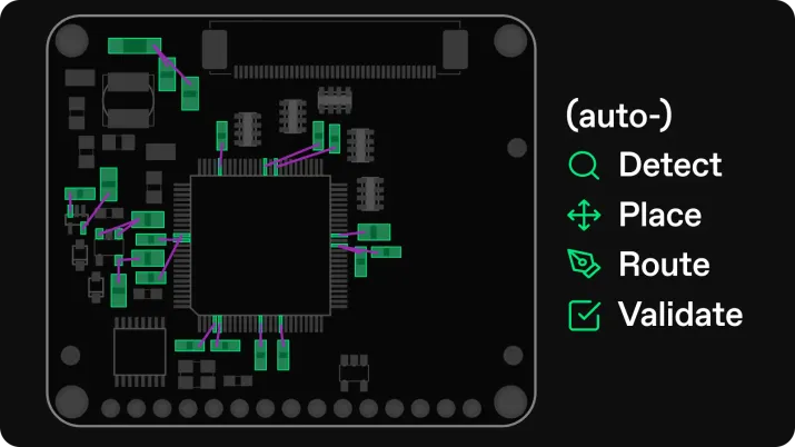

Getting the most out of working with AI requires a shift in traditional workflows, and a shift in thinking. For example, the most productive software engineers that leverage AI have had to learn how to prompt for good code generation, how to review, and where AI can be trusted / where it cannot. As with any other tool, using it well is a skill in and of itself.
Quilter is no different in this regard. In order to be helpful, it must be given sufficient information and constraints, and it must be applied within it’s limits. Our process for working with designers reflects this directly by breaking the process into three major steps. 1: preparation of the board and constraints, 2: running the tool and 3: design review + clean-up. We followed this same process when designing these two boards.
Preparing the Circuit Design
For this design, we decided to directly re-create the NXP i.MX 8M Mini reference design. We tackled both the baseboard and the SOM modules. NXP provides direct design resources in the form of full schematics and CAD files for both boards - designed in Cadence Allegro. Our goal was to leave the schematic identical, and prove out just the layout portion.
At the time that we started this project, we did not yet have support for Cadence tools - so we started by first converting to Altium.
Creating The Schematic
As with any design, everything starts with the schematic. Quilter uses the schematic to populate signal constraints throughout the board. For example, bypass capacitor assignments, high current nets, crystal oscillators, and component groups can be quickly identified.
While Quilter does not require designers to drastically change how schematics are drawn today, some tips are still helpful.
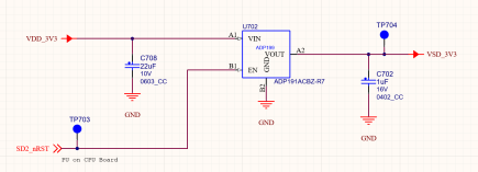
For example, bypass caps are auto-detected when they are explicitly connected to a component pin and ground (see C702 and C708 below):
We used net directives to define net classes for power and impedance controlled nets. This allows easy specification of net-specific requirements once the design is uploaded to Quilter:

It is also helpful to segment components into individual sub-circuits that can be grouped together. This can be done with either a hierarchical schematic approach or, by adding blanket directives in the schematic, such as this 3.3V supply:
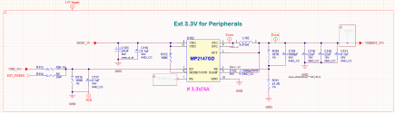
These directives allowed us to generate rooms, which would be manually placed on the board later on in order to allow us to control the floor plan of the board.
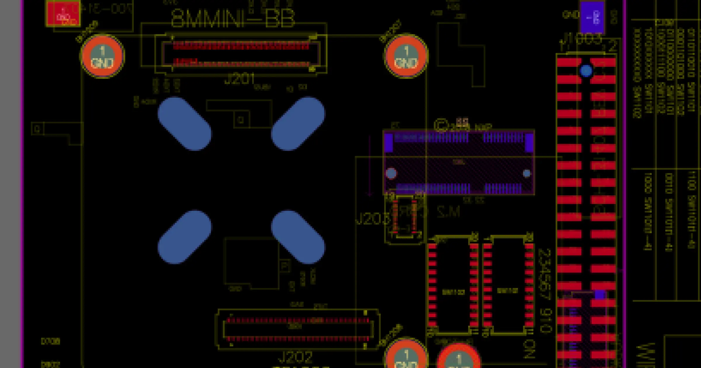
Setting Up The Board File
First, the board outline must be defined, and any fixed-location components should be placed. For example connectors, buttons, switches, mechanical cut-outs, mounting holes etc should all be pre-placed. This forces Quilter to treat these as a constraint.

Finally, on complex boards is it beneficial for the user to still control the floor plan of the board. This can be done with rooms, using the hierarchical schematics and blanket directives defined in the schematic:

Quilter is responsible for components placed off the board, while those that are already placed remain as a constraint.
Let Quilter Determine Stack-up
Quilter is able to determine a stack-up for the board automatically by trying a number of possible stack-ups from different manufacturers. For projects of this complexity though, users often prefer to specify and control the stack-up explicitly - which Quilter can use during the generation process.

Building the Computer
For this build, we partnered with Sierra Circuits for the fastest possible turn-around time while meeting the tougher fabrication constraints of especially our SOM. Regrettably, we got hit by out of stock parts (classic issue) and so had to make a couple of swaps on connectors, and had to bail on including the WiFi module. Of course we were just re-doing an existing design - had it been a new design the parts wouldn’t have been designed-in in the first place. Still, should have checked sooner!
Sierra quoted and delivered on 3 day turn for bare board and 3 days on assembly. On the baseboard things went smoothly and we had our boards in hand pretty quickly.
The SOM was trickier due to the 2mil trace/space - as Sierra had to kick in to a more advanced process. That ran a bit longer.
The thing that never happens though, is: both boards worked on first bring-up. No revs, no respins, no re-work.
Now what really helped us here is that we built both of these boards ahead of time - straight from the human design. So we verified that the circuit is good, no issues with Cadence → Altium translation, no issues with parts we sourced, and we learned how to flash the designs.
Designing with AI
Project 27 didn’t just compress a schedule; it reframed what “done” means in hardware design. By encoding engineering judgment as executable constraints and partnering directly with Sierra Circuits for real-world manufacturability, the team closed the loop between concept and copper. Both boards booted on first power-up, not because of luck, but because verification was built into every phase—from schematic definition to HDI fabrication.
The 400-hour problem was never just about time. It was about translation: how long it takes for an idea to become a physical, testable artifact. Project 27 showed that when humans teach systems what correctness looks like—and when fabrication moves in lockstep with design—that translation can happen at the pace of understanding itself. For the next generation of engineers, that’s the new baseline: not faster tools, but smarter definition.
To look into what it takes to set-up Quilter to perform these jobs, click into the next article here.