
Even the most constraint-aware routing engine produces a first pass that is technically correct but not yet optimized. Clean-up isn’t about fixing what went wrong; it’s about resolving what the software couldn’t yet infer.
For example, trace width versus thermal relief, via stub delay versus phase alignment, polygon area versus IR drop are still judgment calls made by experienced engineers. Each manual refinement becomes the next candidate for automation. In this sense, clean-up is the proving ground where human intuition and algorithmic precision meet, and where the next iteration learns what “good” actually looks like.
Quantifying the Collaboration
The cleanup phase of Project 27 wasn’t a rescue operation; it was a precision pass. Of the 38.5 total design hours, 26.5 were spent refining parameters the routing engine had already executed within tolerance. The table below breaks down how human engineers and automated constraint logic divided that work:
Traditional post-layout cleanup for boards of similar complexity averages 70–90 hours. Project 27 reached closure in under 30 hours—an efficiency gain of roughly 3×—while maintaining full signal-integrity validation.
Clean-Up Process for Project 27 Single Board Computer
Baseboard Design
The table below breaks down the most important cleanup that we had to do and how long each segment took.
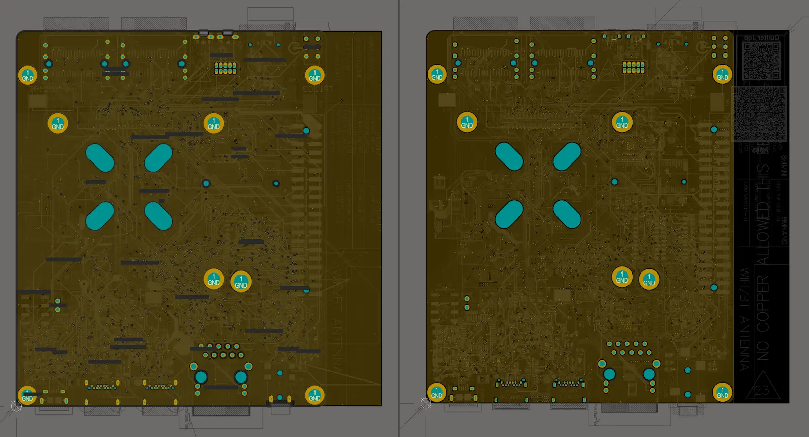
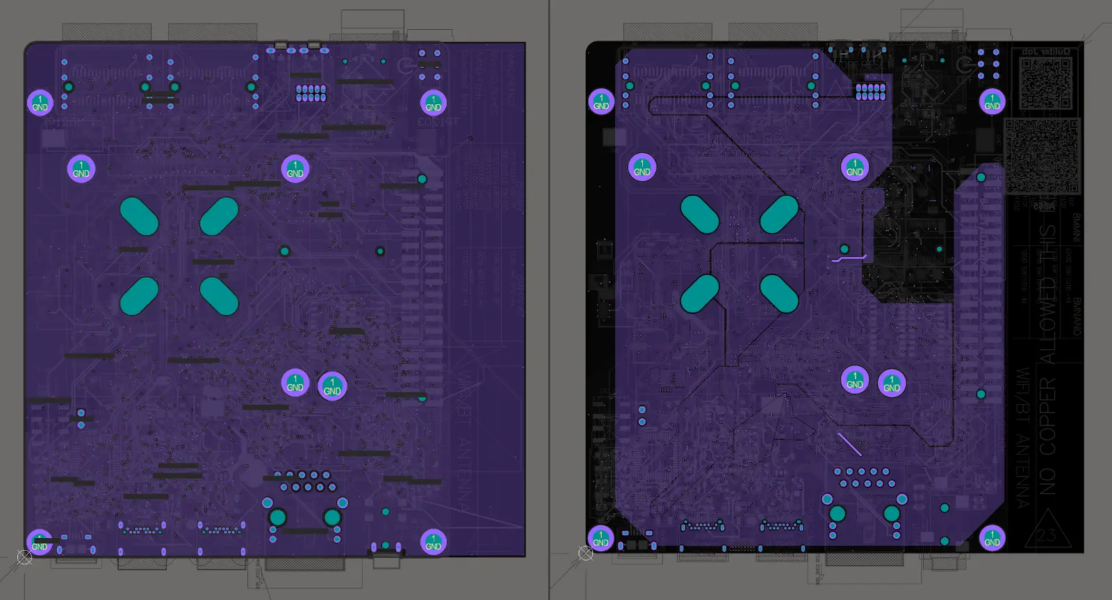
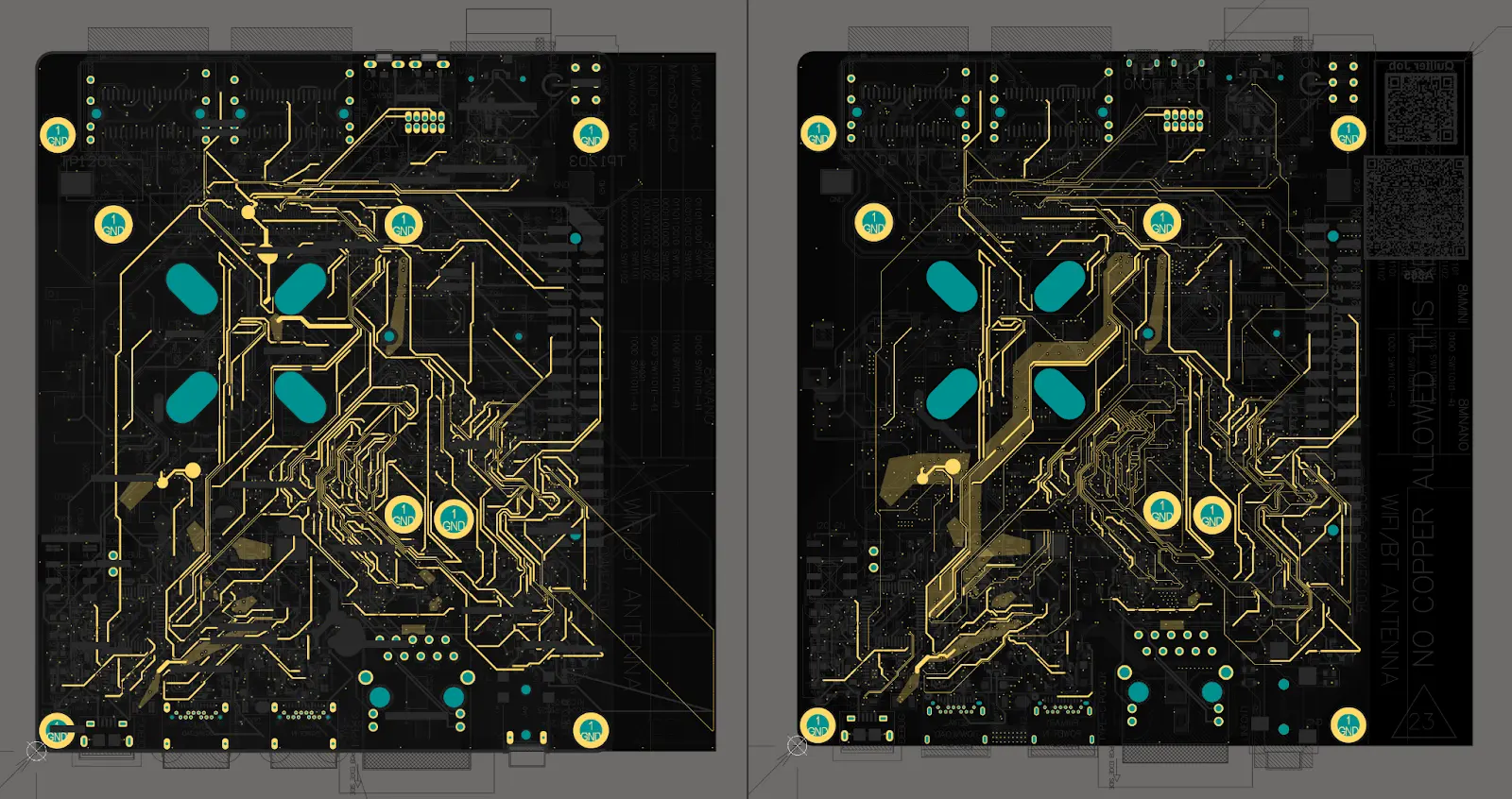
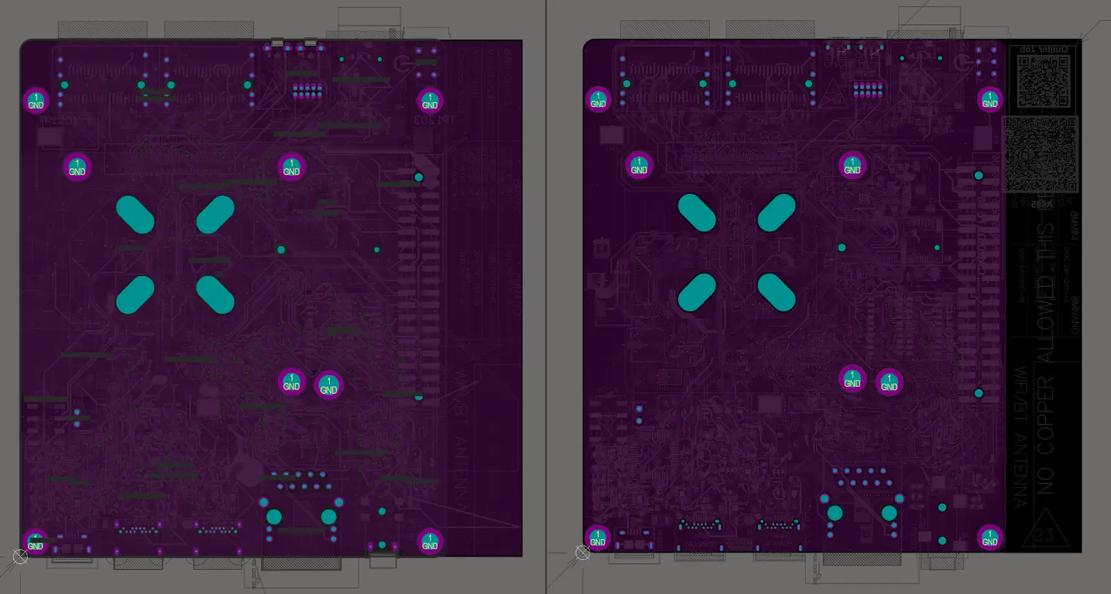
You can see this visually as well as you compare the different layers. For the pictures below, left is Quilter output, right is cleaned up. Included just the layers with routing (the plane layers are boring / unmodified).


System-on-Module (SOM) Design
The table below shows the cleanup time breakdown for the SOM. This is focused just on the actual copper, component placement changes to make the board function. Doesn’t include other labor done to prepare fab files - as that is parity with the current workflows.
We noticed that the majority of our cleanup time was spent on polygon pours and length tuning. The biggest reason that length tuning took substantial time, is that we had ignored via delay in Quilter. Once vias were accounted for, there was significant delay added and length tuning had to be re-adjusted. It will be a big win for us to add a via propagation delay model to the length tuning engine to avoid this in the future.
The other major time sink was power polygons. Again, by human judgement, we wanted larger polygons to be comfortable with the power distribution than Quilter had generated. So we took some substantial time to make room for those and enlarge them. We’ll be focused on improving this within Quilter. See “lessons learned”.
Finally, you’ll notice that most traces are wider in the Quilter solution than the cleanup. This was because we had run an experimental trace inflation algorithm to spread traces out more and increase margin.
Testing the computer
After first boot, the i.MX 8M Mini system ran a full suite of functional checks. Debian Linux loaded successfully, launching browser and desktop environments without instability. Standard NXP demo applications, including the onboard machine learning inference and GPU rendering tests, executed as expected, confirming both compute and graphics subsystems were stable under load.
Network validation followed: sustained Ethernet upload and download performance met spec across multiple file transfers. Peripheral testing included camera capture and audio recording, with synchronized playback verified through video output.
Initial functional testing already confirmed that every major interface, from silicon to application layer, behaved exactly as designed.
The Human Learning from Clean-up
Every change made during cleanup was logged. Widened polygons, corrected length-match deltas, via-delay offsets, and copper-balancing parameters were written back into the constraint library. On the next project cycle, Quilter will preload those preferences automatically.
Preliminary tests already show that learned corrections reduce cleanup time by another 20–30 percent. In effect, cleanup doesn’t just finish a board—it trains the next one.
Micro-Case Examples
- Polygon refinement: On the SOM, the system initially left 9 mil clearance between high-current pours; widening to 14 mil reduced IR drop by 12 percent.
- Length tuning: Within the DDR4 group, engineers corrected a 42 mil skew—well inside the margin but now stored as a pattern the router can anticipate.
- Via delay modeling: After characterizing 18 ps per via pair, Quilter began auto-adjusting serpentine routes to pre-compensate for delay, improving phase alignment by 6 percent.
Each micro-correction became a rule. Each rule became a reusable insight. Together they form the dataset that steadily closes the gap between “correct” and “complete.”
Project 27: Design Finalization
Project 27 began as an experiment in compression—an attempt to see if the work of ten weeks could fit inside two days without losing technical integrity. It ended as proof that hardware can now move at the pace of software.
By translating schematic logic into executable constraints, partnering early with Sierra Circuits for fabrication alignment, and validating through full functional bring-up, the team demonstrated that automation in PCB design isn’t abstraction—it’s acceleration. The computer didn’t replace the engineer; it amplified engineering judgment, executing it at scale and with measurable precision.
The results of 38.5 hours from schematic to working boards, zero respins, and verified performance across every subsystem mark a shift in how hardware will be built going forward. The next generation of boards won’t just be drawn faster; they’ll be defined smarter.